Place Clearance
Overview of the Place Clearance Setting window
Adding cable tray clearances helps to ensure the cable tray as the required accessibility for access. The depth and width of the clearance zones are customizable and may be placed on any of the four sides(top, bottom, left, and/or right) of the cable tray elements. The clearance zones may be placed between connected cable tray elements, on an entire run, or a user-defined selection.
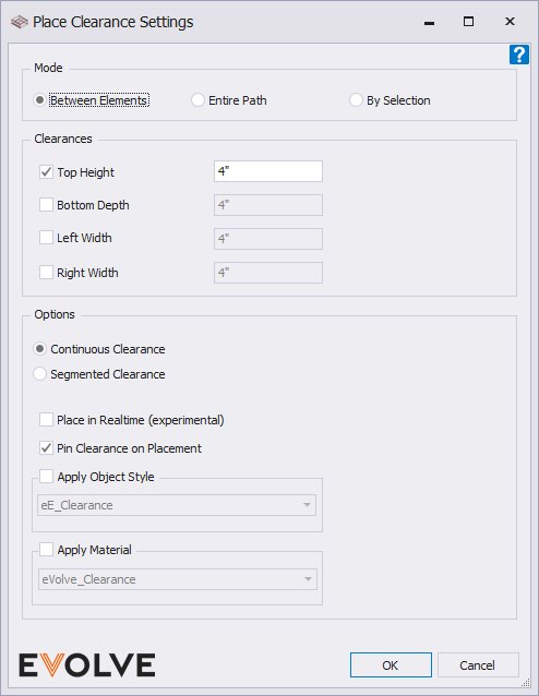
Mode Panel
- Between Elements - Places a clearance zone between two selected elements.
- Entire Path - Places a clearance zone throughout the entire connected cable tray run. Stops at all multi-directional elements with two or more connectors.
- By Selection - Places a clearance zone on the user-selected elements.
Clearances panel
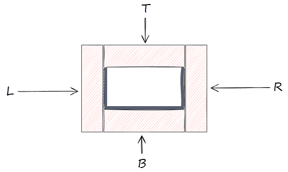
- Top Height (T) - enables the clearance zone above the cable tray element.
- Bottom Depth (B)- enables the clearance zone below the cable tray element.
- Left Width (L)- enables the northern/westwardly clearance zone of the cable tray element.
NOTE: "Left" is always determined by the starting cable tray element and in relation to project north. - Right Width (R) - enables the southern/eastwardly clearance zone of the cable tray element.
NOTE: "Right" is always determined by the starting cable tray element and in relation to project north.
Options panel
- Continuous Clearance - this option creates an uninterrupted extrusion based on the selected Placement Mode.
- Segmented Clearance - this option creates separate "clearances" for each element.
- Place in Realtime checkbox - when enabled, this option attempts to automatically update clearances on host elements as they are edited.
- Pin Clearance on Placement checkbox - when enabled, placed clearances are also pinned, this option is enabled by default.
- Apply Object Style - when enabled, this option defines the object style of the modeled clearance. If blank, the family type of the eVolve clearance is a Cable Tray Fitting.
- Apply Material - when enabled, this option defines the material that is applied to the modeled clearance. If blank, no material is applied.

Placing Cable Tray Clearances Between Elements
- From the eVolve ribbon, in the Clearance panel, click Place Clearance.
- From the Place Clearance Settings window, in the Mode panel, click Between Elements and select the desired settings in the Clearances panels and Options, then click OK.
- From the drawing area, click the starting cable tray element for clearance to start.
- From the drawing area, click the ending cable tray element for clearance to stop.
Placing Cable Tray Clearances on an Entire Path
- From the eVolve ribbon, in the Clearance panel, click Place Clearance.
- From the Place Clearance Settings window, in the Mode panel, click Entire Path and select the desired settings in the Clearances and Options panels, then click OK.
- From the drawing area, click a cable tray element in the desired run.
Placing Cable Tray Clearances By Selection
- From the eVolve ribbon, in the Clearance panel, click Place Clearance.
- From the Place Clearance Settings window, in the Mode panel, click By Selection and select the desired settings in the Clearances and Options panels, then click OK.
- From the drawing area, select the desired cable tray elements.
