Insert Offset

Insert Offset

Summary
With Insert Offset, you can quickly add an offset with specified angles and offset distances on RFA MEP elements.
- eVolve Electrical tab ⮞ Quick Tools panel ⮞ Insert Offset button


Limitations
While it may work most of the time, as a rule of thumb, you should not perform the offset function in a 3D view. Offsetting works best in a Callout, Elevation, Plan, or Section View; depending on how things are drawn and rotated in a 3D view, you may encounter an error in a 3D view that would not appear in any other type of view.
Usage
- From the eVolve Electrical ribbon, in the Quick Tools panel, click the Offset menu and select Insert Offset.
- From the Insert Offset window, in the Offset Type panel, choose the type of offset you would like to perform; various options within the Offset Values panel below are enabled and/or disabled.
- From the Offset Values panel, based on the controls that are enabled, define the offset distance and, if necessary, the offset direction.
- From the Settings panel, define the Target Angle and, if necessary, adjust the remaining options, such as modifying the Fallback Angles or setting the Isolate in a Temporary View and Continuous Placement options.
- Click OK.
- From the drawing area,
- Select the straight element(s) to offset and click 'Finish' from the Options Bar.
- Click the insertion point, this is the point along the run at which the offset will start.
- Click the quadrant to offset the run. The run is offset.

What do you mean by quadrant?
- I have created a graphic to better illustrate what's going on. However, after selecting the insertion point (Step B above) for the offset, imagine the straight is cut, and you are standing at the end of the run looking out. Also, the insertion point has been divided into four quadrants. The example below could be a Horizontal Offset or Rolling Offset; and since most of the information has been specified in the Insert Offset window, the quadrant tells EVOLVE the section of the straight to offset and the direction in which to offset that section.
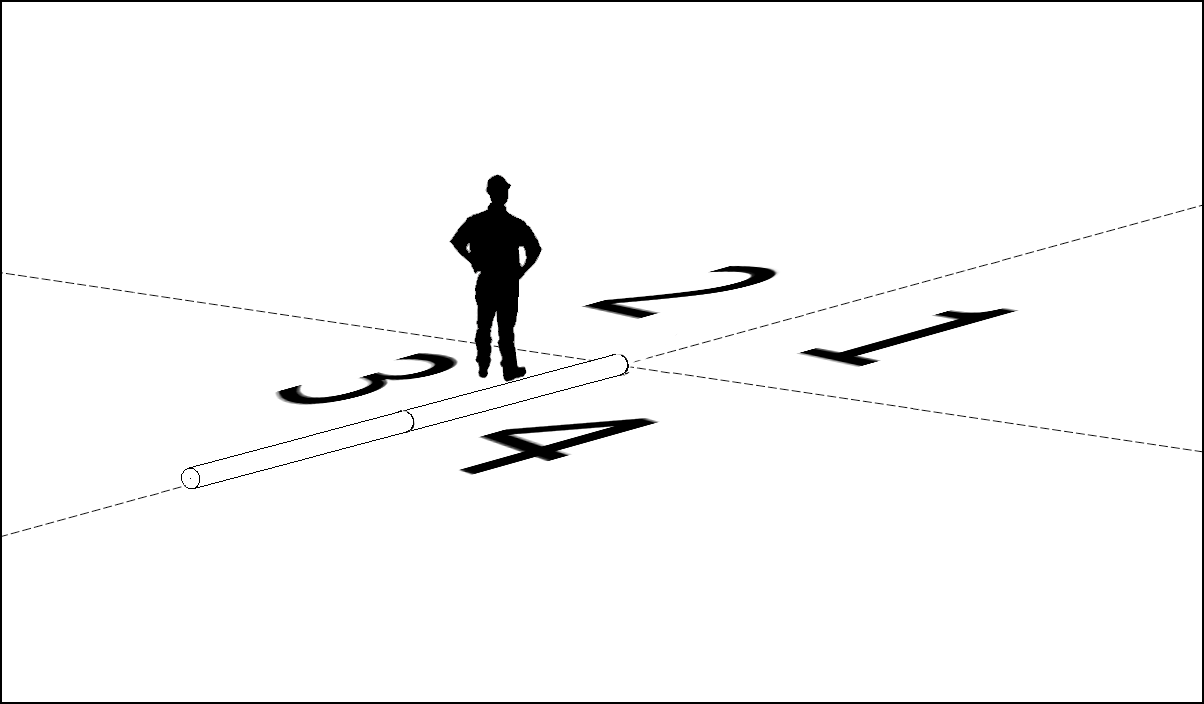
For this example, let's say we're going to create a rolling offset with the following values
- Vertical Offset - 3' - 0" - Up
- Horizontal Offset - 4' - 0"
Selecting quadrant #1 would create this offset to the right, and selecting quadrant #2 would create it to the left. So, let's now look at Quadrants 3 and 4, but first, remember when I said, "Imagine the straight is cut, and you are standing at the end of the run looking out." We need to spin this around.
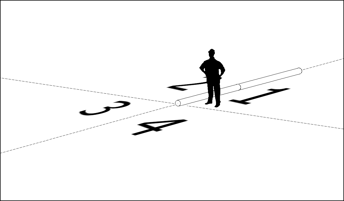
Selecting quadrant #3 would offset the other section of the run to the right, and selecting quadrant #4 would offset the other section of the run to the left.

Window Overview
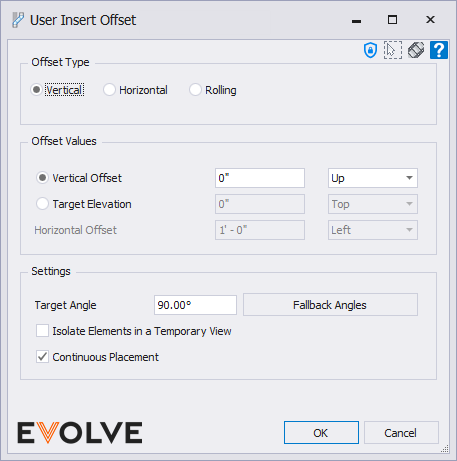
The Insert Offset window
Offset Type panel
- Vertical radio button - when selected, a vertical offset along the Z axis is produced, i.e., if the offset were displayed in an Elevation View, the offsetting direction would be either up or down.
- Horizontal radio button - when selected, a horizontal offset along either the X or Y axis is produced, i.e., if the offset were displayed in a Plan View, the offsetting direction would be either left or right.
- Rolling radio button - when selected, a rolling offset along the Z axis and either the X or Y axis is produced. The offset that's produced offsets both vertically and horizontally, i.e., if the offset were displayed in a 3D View, the offset could be spun in a way to where you can easily see it offsetting in both directions.
Offset Values panel
- Vertical Offset radio button
- Text box - used to specify the distance of the elevation change. This field only accepts positive numerical values.
- Menu - used to specify whether the offsetting direction is Up or Down.
- Target Elevation radio button -
- Text box - used to specify the final elevation of the offset elements. This field only accepts positive numerical values.
- Menu - used to specify whether the offsetting direction is Top or Bottom.
- Horizontal Offset radio button -
- Text box - used to specify the distance of the direction change. This field only accepts positive numerical values.
- Menu - active when in an Elevation or like View and is used to specify whether the offsetting direction is Left or Right.
Settings panel
- Target Angle text box - defines the initial angle that EVOLVE will use when attempting to create an offset. If the offset cannot be produced with the given parameters and additional angles exist ("fallback angles"), then EVOLVE will attempt to create the offset using the angles listed in the "Fallback Angles" list.
- Fallback Angles button - used to edit the list of "fallback angles" the feature may use.
- Isolate Elements in a Temporary View checkbox - when checked, the selected elements will be isolated in a temporary view while performing the offset function. After the offset function is complete, the temporary view will close automatically.
- Continuous Placement checkbox - when checked, the command stays active after the element(s) are offset; press the ESC key to end the command.
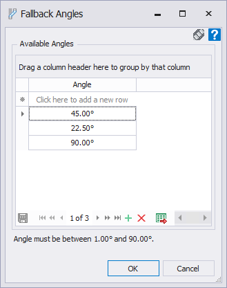
The Fallback Angles window
The Fallback Angles window allows for specific angles to be added to the Available Angles list. If the requested offset cannot be produced at the desired Target Angle and if the Available Angles list is populated with angles less than the Target Angle, then EVOLVE will cycle through the list of angles until it finds an angle in which the offset can be produced.
Adding an angle
From the grid, click into the top row and start typing, or from the Data Navigator located at the bottom of the grid, click the Add new button 
Deleting an angle
From the grid, select the row containing the desired angle, then from the Data Navigator located at the bottom of the grid, click the Delete Selected button 

Tips and Tricks
EVOLVE will attempt to offset elements with the following constraints:
- The element must belong to the following Revit categories:
- Cable Tray
- Conduits
- Ducts
- Pipes
