Cabling Families
![]() Updated 2 years ago
by
Adam Heon
Updated 2 years ago
by
Adam Heon
Our included families, which are preconfigured to use the Auto-Routing feature, can be found in the In-Wall Rough category of the family browser as Auto-Route Type 1 and Auto-Route Type 2. These families have been included as starting points to be further customized to each users individual requirements.
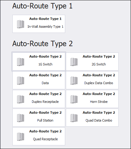
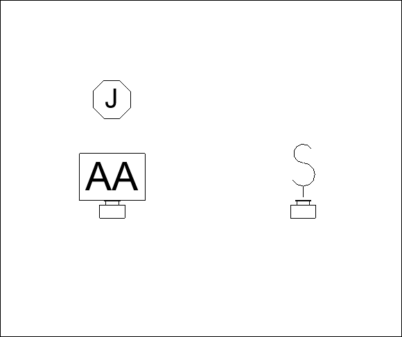
The main difference between the two families is that the Auto-Route Type 1 family uses text for symbols, the Type 2 family uses standard symbols (See Below). The location of the text and symbols is also adjustable within the families, including the spacing of multiple symbols on a part.
Customizing the In-Wall Families
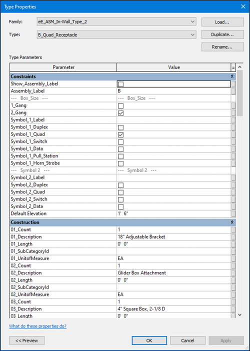
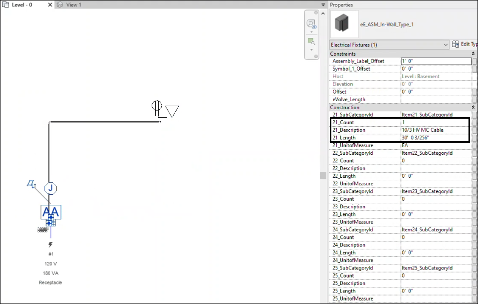
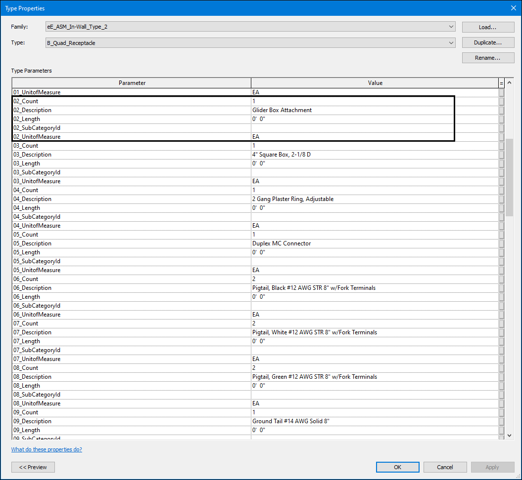
The In-Wall Families can be used as they appear in the library or can be further customized to the needs of each project. Symbol offsets can be adjusted in the Properties Palette, while the majority of other options will be found in the Type Properties. In Type Properties, box size and symbols can be changed. Under the Construction Section, additional part names and descriptions can be added to each type to essentially make each type an assembly, but only when it comes to scheduling purposes. When properly done this way, all parts in the type will report on schedules and boms when placed in a project.
Main Requirements of Families for Auto-Routing
The Auto-Routing feature is not confined to using the preconfigured eVolve In-Wall families. As long as a couple of required items are included in the build, almost any part can be modified to use Auto-Routing.
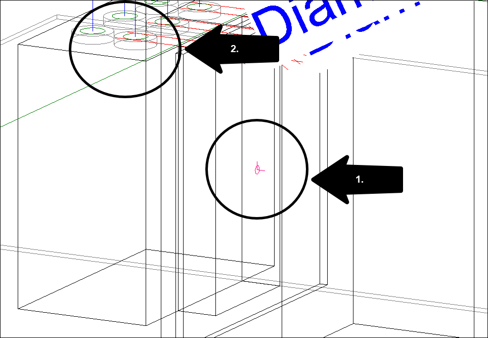
Requirement 1:
The part must contain a properly aligned face node.
Requirement 2:
The part must contain at least one conduit connector
Modeling Note
When using the Auto-Route feature, the cabling will be assigned to the starting device,which is the first object clicked when beginning to draw cabling between two devices.