Adjusting top clearance for equipment in a 3D view
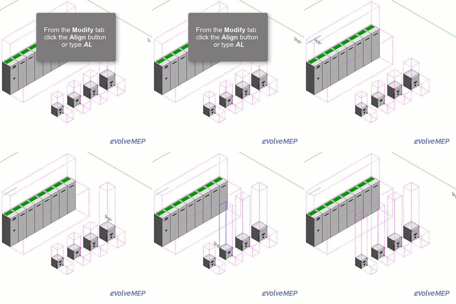
You may also align the top clearances while in a 3D view. For instance, if the top clearance for a specific element is at the correct height, the top clearance for other elements may be adjust to match.
- In the 3D view, from the ribbon, click the Modify tab then click the Align button
 in the Modify panel or type AL while in the 3D view.
 - From the model, click the appropriate equipment’s top clearance to set the reference height (the height to which other elements will trim or extend to).
Before clicking, hovering the pointer until a solid line appears, click the solid line to set the reference height.
- Click the top clearance for other elements.
Before clicking, hovering the pointer until a solid line appears, click the solid line to trim or extend the top clearance.

To align multiple elements, after starting the align command, check the Multiple Alignment checkbox in the Options Bar.
Relevant Articles
Enabling/disabling the top clearance of equipment
Manually adjusting the top clearance of equipment
Adjusting the top clearance for equipment from a section view
